
Views: 233 Author: Reshine Display Publish Time: 2024-02-22 Origin: Site


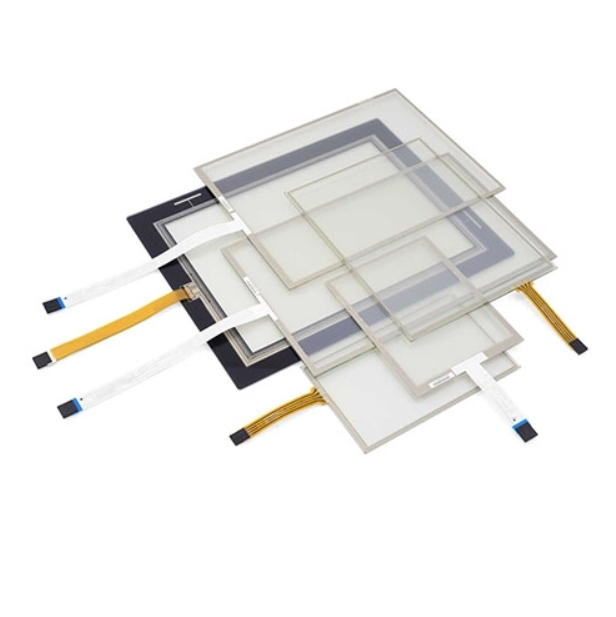
The 8-wire resistive touch screen structure is identical to the analog 4-wire resistive touch technology, which has two transparent conductive sheets facing each other. One sheet has electrodes on the right and left sides, while the other has electrodes on the top and bottom. Voltage is applied to the sheet with electrodes on the right and left sides, and a touched point in the X direction is recognized while the voltage is monitored by the other sheet. Then, a voltage is applied to the sheet with electrodes on the top and bottom sides, and a touched point in the Y direction is identified as the voltage is monitored by another sheet.
In contrast, analog 8-wire resistive technology has additional wirings attached to each electrode. Each electrode receives one additional wire. These additional wirings function as auxiliary electrodes, measuring the voltage on each electrode and relaying the information to the controller. Four more sensing wires will be added, two on each layer. These additional sensing sites primarily serve to stabilize the system and prevent drift caused by environmental changes.
Before using resistive technology, it must go through a "calibration" process. The aim is to match the touched points on a touch screen to the positional data of the pointer on the display. Calibration is the process of aligning a touch screen's coordinates with the display behind it. Analog 4-wire resistive technology required calibration not only at the start, but also on a frequent basis, because touch-detecting points gradually drifted out of alignment due to changes in resistance values on wiring and/or connector parts over time. In analog 8-wire resistive technology, auxiliary electrodes automatically measure the voltage on each electrode and provide the results to the controller. The voltage measured during contact is converted into locational information in the relative ratio to the feedback voltage. This method cancels the effects of voltage changes at electrodes, eliminating the need for recalibration. So, analog 8-wire resistive technology outperforms analog 4-wire resistive technology because it automatically corrects alignment and eliminates the need for recalibration.
The main disadvantage, similar to 4-wire technology, is that one coordinate axis uses the outside, flexible coversheet to create a uniform voltage gradient, while the inner or bottom layer serves as the voltage probe. The constant flexing of the outer coversheet changes its resistance with use, reducing the linearity and precision of this axis.
Following the 1990s, the need for 8-wire resistive touch panels decreased. This is due to advances in resistive touch screen design and materials, and current 4-wire resistive touch displays can be used in many applications for an extended period of time without needing to be calibrated. Although the four additional sensing sites help to stabilize the system against drift, they do not improve the screen's durability or life expectancy. As a result, 8-wire systems are typically seen at sizes of 10.4 inches or bigger, with significant drift.
In 5-wire resistive touch screens, the bottom sheet has equipotential distribution in both the X and Y directions; the top sheet measures the voltage of the bottom sheet. The core electronics are built around the glass bottom layer, with a consistent voltage delivered to the top plastic layer. A touch creates an electrical contact between the top and bottom layers. The voltages at the four corners of the glass vary depending on the point of contact, and a complicated algorithm in the controller is used to calculate the x-y coordinate of the point of contact.
The five-wire resistance touch screen has the following advantages: the glass substrate is reasonably firm and difficult to bend, and the ITO attached to it can be fully oxidized. The glass substance does not absorb water, and its expansion coefficient is extremely similar to that of ITO. The deformation will not harm the ITO. The ITO on the upper layer serves merely as the lead electrode, and no current flows. Therefore, equal conductivity is not required. Even if it is damaged by deformation, it will not cause "drift" of the resistance screen.
The electrodes of the five-wire resistance touch screen cannot be lead out from the four sides by conductive strips, as this would result in a short circuit. The electrodes are spread throughout the touch screen in various resistance patterns and then led out from the four corners. These patterns are employed to linearize the voltage gradient in the touch screen's X and Y directions, allowing for easier coordinate measurement.
When the five-wire resistive touch screen is operational, UL applies the driving voltage drive and LR is grounded. The contact's X and Y coordinates are measured in the two steps listed below:
A. Calculate the Y coordinate, then apply the driving voltage vdrive to the ur electrode while grounding the LL electrode and using the moveable electrode as the lead-out terminal to measure the voltage at the contact point.
B. Calculate the X coordinate and apply the driving voltage to the LL electrode, while grounding the ur electrode and using the moveable electrode as the lead end to measure the voltage at the contact point.
The 5-wire resistive touch screen tries to overcome the limitations of the 4-wire resistive touch screen. The five-wire resistive touch screen's structure is as follows: the X and Y electrodes are entirely manufactured on the ITO layer bonded to the glass substrate, while the higher layer's ITO is only employed as the movable electrode. The X and Y electrodes of the bottom layer ITO emit UL, ur, ll, and LR from four corners, and the top layer active electrode is added, resulting in five lines in total.
Analog 5-wire resistive sensors, like analog 4-wire resistive technology, are made up of top and bottom sheets that face each other with a gap in between. In contrast to analog 4-wire resistive technology, analog 5-wire technology places electrodes on four corners of the bottom sheet.


